

The design, operation, and diagnosis of charging systems and battery control modules
Early Batteries
It is not certain exactly when the first battery was conceived but Allesandro Volta is credited with developing the first battery. Archaeological digs have discovered devices that could possibly have been used to store electrical energy but it was Volta’s experiments in the late 1700s and early 1800s that paved the way for the modern battery. Volta discovered that certain fluids would generate a continuous flow of electricity when used as a conductor. This discovery led to the the invention of the first voltaic cell, what we now call a battery. He also learned that he could increase the voltage output if he connected the cells in a series. Continuing in his experiments he found that different metals have different electron affinities so that if he used silver and zinc immersed in electrolyte he would get different voltages than if he used lead and tin.

Lead acid batteries
Lead acid batteries are the oldest rechargeable batteries in existence. The lead acid battery was the first rechargeable battery for commercial use. Lead acid does not lend itself to fast charging. Finding the perfect voltage limit is critical. A high voltage (above 2.4v per cell) produces good battery performance but shortens battery life due to corrosion on the positive plate. Conversely a low voltage charge is subject to sulfation on the negative plate. Finding the ideal charge rate is where modern charging equipment comes in which we will discuss later in this article. Lead acid batteries also to not lend themselves to deep cycling. A full discharge causes extra strain on the battery and each cycle robs the battery of some service life so keeping the battery charged up is critical to its service life. A typical sealed lead acid battery will have approximately 200 to 300 discharge/charge cycles. Corrosion of the grid plates of the positive electrode is the primary reason for this relatively short cycle life. Lead acid batteries have one of the lowest energy densities making it unsuitable for portable devices and performance at low temperatures is diminished. On the plus side however the self-discharge rate is about 40% per year which is among the best for rechargeable batteries. By comparison ni-cad batteries self-discharge this same amount in about 3 months.
Why AGM?
AGM or absorbent glass mat battery technology became popular in the 1980s to reduce weight and improve reliability. The sulfuric acid is absorbed by a very fine fiberglass mat which in turn make the battery spill proof. This also allows shipping without hazardous material concerns. AGM batteries have very low internal resistance, can deliver high currents on demand and offer a relatively long service life. AGMs are maintenance free as well. The leading advantages of AGM batteries are a charge rate that is up to five times faster than the typical flooded lead acid battery and the ability to deep cycle. These characteristics make it the ideal battery for today’s modern high electrical load vehicles. AGM batteries do not like heat which is why typical installations are in the trunk area and not in the engine compartment.
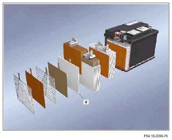
typical AGM battery
What do the numbers mean?
CCA or cold cranking amps is a rating used in the battery industry to define a battery’s ability to start an engine in cold temperatures. Generally speaking, it is easier to start an engine in a warm environment than in a cold one. The rating refers to the number of amps a 12-volt battery can deliver at 0°F for 30 seconds while maintaining a voltage of at least 7.2 volts. The higher the CCA rating, the greater the starting power of the battery.
RC or reserve capacity is a general indicator of how long a new, fully charged battery can continue to operate essential accessories if the vehicle’s alternator fails. It identifies how many minutes the battery can deliver a constant current of 25 amps at 80°F without falling below the minimum voltage, 1.75 volts per cell, needed to keep your vehicle running.
Amp Hour or C20 is an indicator of how much energy is stored in a battery. It is the energy a battery can deliver continuously for 20 hours at 80°F without falling below 10.5 volts.
First things first
In order to conduct a proper charging and battery systems test we must first evaluate the battery’s state of charge. Since the release of the model 204 it is now possible to evaluate the batteries state of charge via the intelligent battery sensor (IBS) data stored in the SAM and the CAN bus keep awake unit recognition in the central gateway (CGW).
IBS design and function
The IBS is attached directly to the negative pole of the battery via the pole terminal. Along with the terminal, the mechanical part of the battery sensor is comprised of the shunt and ground pin. The shunt is attached to the vehicle’s load path and is used as a measuring resistor to measure the current indirectly. On the ground pin, the existing ground cable can be conveniently attached. The electronics are located in a molded housing with a connector as an interface for energy management. It records the voltage of the on board electrical system battery and the on board electrical systems power consumption. These measurements are used by the battery sensor to calculate the internal resistance of the on board electrical system battery. A temperature sensor integrated into the battery sensor measures the temperature at the negative terminal. This is then used to calculate the inside temperature of the on board electrical system battery.
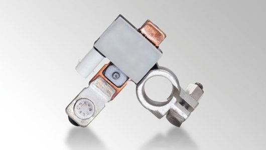
the Intelligent battery sensor is typically located on the negative post
The battery sensor provides the following on board electrical system values to the rear SAM control unit over the on board electrical system.
- Voltage
- Interior temperature
Using a scan tool you can access not only the IBS data in the rear SAM but also may be able to locate the source of the reason for the low state of charge in your battery. Below is just one of the menu options you’ll find to diagnose the battery.
If you have a case of a battery discharged, vehicle does not start complaint you would read out the fault menu of the IBS. Say perhaps the following entries are present:
- Power consumption by standing lights or parking lights
- Power consumption by low beams
You may have an indication of a faulty rotary light switch. If no other faults are found then proceed to charging and testing the battery itself. The battery must be charged using an approved charger (see SSEP catalog located under “MB Equipment” menu of STAR TekInfo). A high quality diagnostic battery charger will determine the internal condition of a battery before attempting to apply a charge to it. The charger applies an AC signal at a known frequency across the terminals and measures the internal conductance to determine battery health before attempting to charge. It is important to complete this step before moving on to testing the charging system of the vehicle. The battery should be fully charged up or replaced if it has been found to be faulty or your charging system data could give you faulty readouts. Correct charging of the on-board electrical system battery, starter battery, and buffer battery helps to ensure that the vehicle continues to start, functions properly, and has optimal battery life. The battery charging period depends on the charge level of the battery. The battery is sufficiently charged when the charging current reading is < 25 A. Most modern day computerized battery chargers will determine the correct charging time and rate and also tell you when the charge is complete.
The Next Step – Convert Mechanical energy into Electrical energy
Now that you have verified a fully charged battery and located any possible sources of battery failure it’s time to check the charging system. As earlier discussed we know that lead acid batteries do not like to be fully discharged so it’s critical for battery life and the vehicles reliability to have the charging system working properly.
The first electric generator was invented by Michael Faraday in 1831. This British chemist and physicist did extensive work in the field of electricity that paved the way for the inventions of the electric motor and transformer. Faraday discovered electromagnetic induction. He found that the electromagnetic effect a current has in one wire is able to generate electricity in another wire. Using this information, he learned how to produce a steady current. He connected two wires to a copper disc. He then maintained a steady current when he switched the disc back and forth between the two poles of a horseshoe magnet. Thus he made his first electric generator. Today’s systems have come a long way from his first invention however the principle is still the same – use the mechanical power from the engine to drive alternator and recharge the batteries and maintain the electrical load of the vehicle.
The earliest vehicles had charging systems fitted with generators. When the engine speed is at idle or at low rpm, the generator has little or no output, and the battery provides all the electrical energy needed for the electrical system. When vehicle speed reaches about 20 mph or engine rpm reaches about 1200, the generator will begin to charge. The output will help the battery with some of the electrical load. (This speed is known as the generator “cut-in” speed.) At higher engine rpm of about 1800, the generator is capable of providing all of the electrical current needed to run the accessories, as well as recharge the battery as needed. Generators will usually provide their maximum output at about 1800 to 2300 rpm engine speed. Normally the pulley diameter of a generator is designed so the engine will spin the generator at, or close to, its ideal rpm, (the rpm at which the generator operates most efficiently.) This rpm is matched to the rpm at which the engine will spend most of its time. A voltage regulator protects the system from overcharging by maintaining the optimum charge voltage. You can see drawbacks to this set up and with the advent of more complex electrical systems a more efficient system was need.
Enter the Alternator
Alternators have the great advantage over direct-current generators of not using a commutator, which makes them simpler, lighter, and more rugged than a DC generator. The stronger construction of alternators allows them to turn at higher speed, allowing an automotive alternator to turn at twice engine speed, improving output when the engine is idling. The availability of low-cost solid-state diodes from about 1960 allowed auto manufacturers to substitute alternators for DC generators. Automotive alternators use a set of rectifiers (diode bridge) to convert AC to DC. To provide direct current with low ripple, automotive alternators have a three-phase winding. There are typically three separate windings of wire in the stator that are all set to so that the AC current that is generated is slightly out of phase in each one. The peaks and valleys of the rising and falling current do not happen at the same time, rather they are staggered a bit. This increases and smoothes the electrical output of the alternator much the same way that a 8 cylinder car runs more smoothly than a 4 cylinder one does – there are more power pulses happening in each revolution allowing more total power and better smoothness.
The process of rectifying the AC current into DC current is handled inside the alternator by something more complex than a commutator – diodes. A diode is a “solid state” device that allows current to flow in one direction only – “solid state” means it does this without any mechanical or moving parts. It relies on the different electrical properties of the materials it is made of to act as a one-way valve for current. By arranging diodes so that current from each of the three stator wires is only allowed to pass in one direction, and by connecting the three outputs together, you get a reasonably smooth and stable DC output without any moving parts. (This arrangement is typically manufactured as a single part and is referred to as the diode pack or diode trio.) This lack of moving parts makes the alternator not only very reliable – but also comparatively inexpensive to build and repair.
Testing
Keep in mind that for some time Mercedes-Benz vehicles/engines have been equipped with alternators which communicate with the ME or CDI engine control via an interface. This results in changes to the system diagnosis and when testing the alternator a distinction is made between the conventional alternator with terminal 61 without interface and alternators with BSS interface or LIN interface. Using Xentry or other compatible scan tool you will want to check control modules for related codes stored as well as freeze frame data to help in your evaluation of the vehicle charging system. You can generally follow the on screen instruction to complete testing of the charging system. Steps included but not limited to will include:
- Recording voltage output at idle and 2500 rpm, both with and without electrical loads.
- Current output at same stated conditions
- Checking all wiring and connections at the battery and alternator.
- An alternator diode ripple test.
A proper analysis of diode ripple is important as a fault with excess diode ripple may mask a problem with otherwise proper output from the alternator. If only one or two diodes have failed, the alternator may still produce enough current to meet the vehicle’s electrical needs, but it may not be enough to keep up with higher loads or keep the battery fully charged. This could cause the battery to run down over time.
Diode failures may also allow AC current to leak into the electrical system. AC voltage creates electrical “noise” that can confuse electronic modules and digital communications. A leaky diode also can allow current to drain out of the battery through the alternator when the vehicle is not being driven. If your testing proves out to have an internal failure of the alternator the repair is as simple as replacement since all components are integrated into one unit.
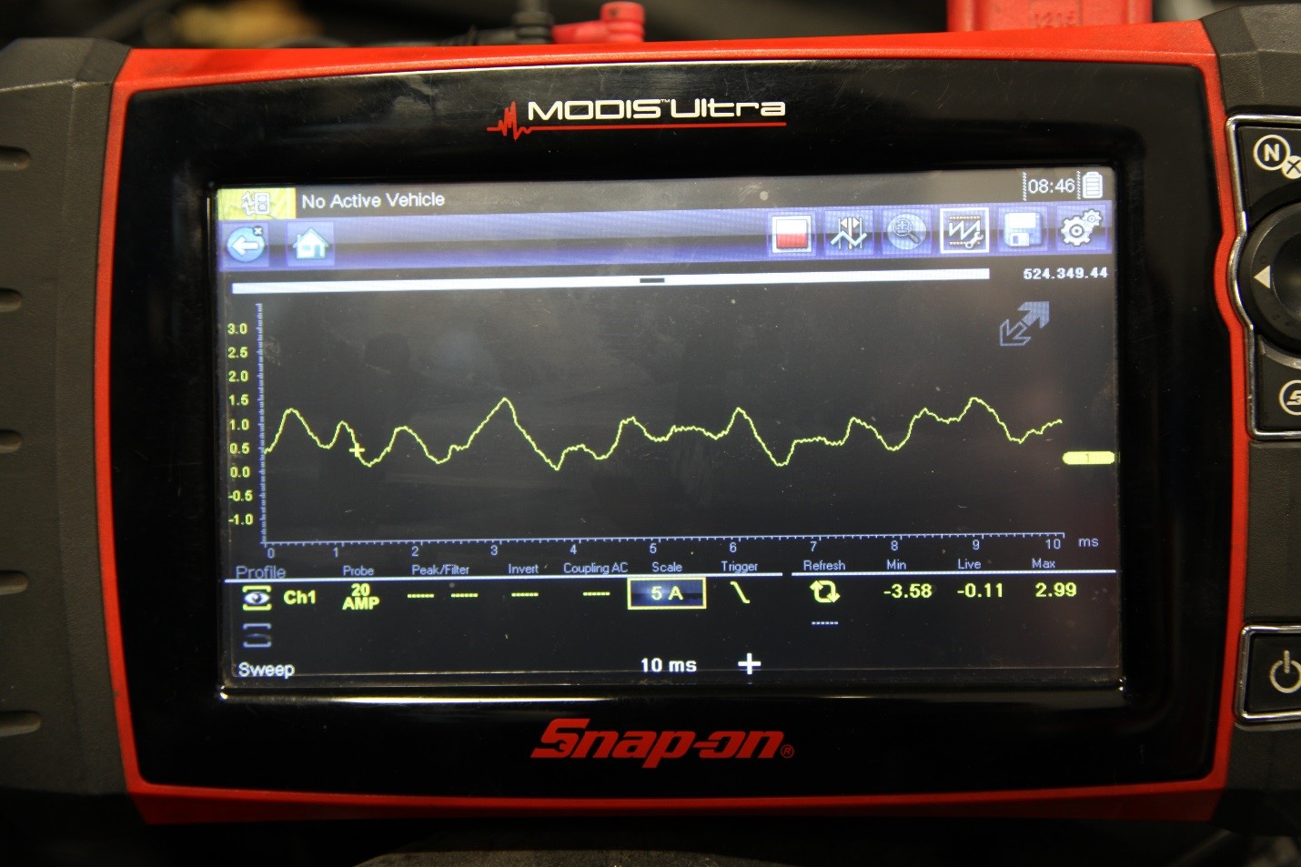
A poor diode ripple pattern
0 Comments